Going Online
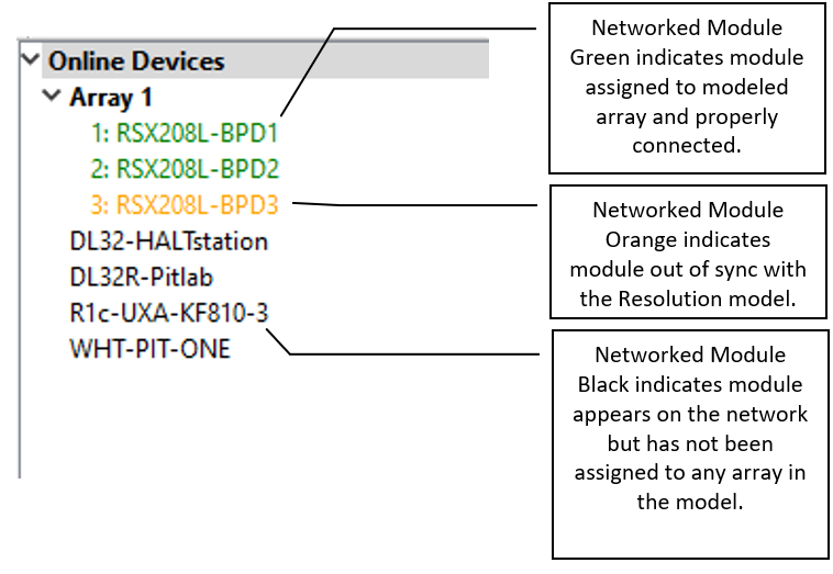
Before going online, be sure your computer is connected to the same Ethernet network as the networked loudspeaker system. Communications is established by clicking Network on the Menu bar and selecting Connect. Resolution 2 will then search for any Adaptive devices on the network and displays them in the Online Devices list. This list will include your computer running Resolution 2.
Radius devices are grouped according to how they are physically arrayed, so if you have assembled an array of two modules in a single vertical column for example, those will be listed as:
Array #
Column 1
EAW-Module-#####
EAW- Module -#####
…….
Column 2
EAW- Module -#####
EAW- Module -#####
…….
..and so on.
If an array does not automatically group; right click Online Devices select Refresh Neighbor List
The names of the individual modules in that Column will be listed in the order they are physically arranged. Stand-alone modules will be listed individually.
Assigning Physical Arrays/Modules to Modeled Arrays/Modules in Resolution
**EAW’s recommended best practice for Radius systems is to create your venue in the Design View and determine the optimum arrays needed to provide the coverage you will need prior to assembling, flying, energizing and connecting to the system. This will ensure you know how the Arrays will need to be configured.
However, this is not required, and you can simply fly the arrays and connect Resolution 2 to your system with a blank Venue loaded if needed.
It is best to at least enter a simple representation of the area you intend the System to cover. Adding arrays in the appropriate positions prior to going online will speed connection time allowing you to upload settings as soon as you associate a modeled Array with its physical Array.
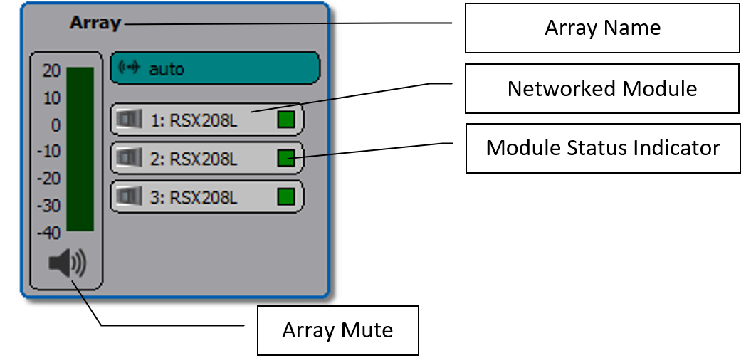
If you have not defined any Arrays in your Venue, then you can simply click on each Array in the Online Devices list and drag them over to the Network Configuration desktop. This will open the Array Assistant dialog. Once you enter the settings and click finish, Resolution 2 will create an icon with the name of the Array, the list of arrayed modules in each Column in the Array, an Array Mute button, Input Level and Gain Reduction meters.
You can edit the X,Y,Z physical location, Min Trim, Max Hang and Aim Angle in the Properties pane while that Array is selected.
If you have created a venue and arrays in Resolution, then “virtual” Arrays and Modules in your model will be displayed in the Network Configuration View as grey boxes. Each module in the array will have a small indicator square that reports each module’s status.
- A question mark indicates that no physical module has been associated with the module in the model.
- A Yellow box indicates a module that has gone offline.
- A Red box indicates a module previously assigned that was not found upon reconnecting to the Network.
- A box that occasionally flashes Green indicates the module is successfully communicating with Resolution.
Unassigned modeled Arrays will have the list of modules or loudspeakers included in the Array while non-arrayed loudspeakers will be shown as individual boxes with only one device listed. Arrays will be shown with the modules in Columns and the meters.
A physical Adaptive or Radius Array in the Online Devices list can be assigned or associated with a modeled Array in the model by simply clicking on the Array in the list and dragging it on to the appropriate modeled Array.
Note: the physical Array and modeled Array must include the same quantity and arrangement of modules).
For example, assume your model includes two RSX212L Arrays and you’ve named them as “Left Array” and “Right Array”. You have assembled two, two-module arrays on-site and physically mounted them in the corresponding positions in your model. Click on an Array in the Online Devices list, observe which physical array has LED lights turned on (be sure Auto Identify is enabled) and drag the Array over and on top of the corresponding Array in the model, i.e., the left physical Array on the “Left Array” in the model.
Proceed with assigning any remaining physical Arrays to modeled Arrays until all Arrays have been assigned.