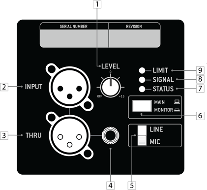
- Level (Gain) Control Adjusts the level of the INPUT signal. Turning counterclockwise will reduce the output level and turning clockwise will raise the overall output level of the speaker.
- XLR Input Connector Balanced XLR input connector for analog input signal.
- XLR Thru (Output) Connector Balanced XLR output connector to daisy-chain input signal to other speakers. This signal comes directly from the input signal and is unaltered by speaker’s internal processing.
- Balanced TRS Connector Balanced 1/4” TRS input connector for analog input signal.
- Line/Mic Switch This switch controls the input sensitivity. For low-voltage signals, such as from a microphone, set the switch to the MIC position. For high-voltage signals, such as from a mixing console, set the switch to the LINE position. NOTE: Utilizing the MIC switch position with a high-voltage signal may cause damage to your speaker – be sure to use the proper switch settings based on the incoming signal strength.
- Main/Monitor Button This button is used to toggle between the speaker’s two pre-defined voicings – MAIN and MONITOR. The MAIN voicing should be chosen when the speaker is placed on a tripod or installed. The MONITOR voicing should be chosen when the speaker is placed on the floor or at its monitor angle – this setting reduces the impact of low frequency floor coupling that occurs when a speaker is placed on the floor, providing a cleaner and more coherent output.
- Status LED Indicator The status indicator will remain lit if the speaker is in functioning condition. If the light blinks, it indicates that the speaker has entered temperature protection mode and must be cooled down and power-cycled before it will function normally.
- Signal LED Indicator The status indicator will turn green when an input signal is detected. NOTE: Low-voltage signals may not be able strong enough to trigger the LED indicator, but may still be heard from the speaker – this is perfectly fine.
- Limit LED Indicator The limit indicator will turn red when the output has reached its maximum level. If the LED blinks occasionally, EAW DynO™ will optimize the output and continue to provide clear output at its maximum volume. If the LED blinks frequently or is lit continuously, reduce the level control (1) to prevent output distortion. NOTE: Only one signal input may be used at a time (2 or 4) – using both at the same time will result in a distorted signal.